


OCH2360
Three-Phase Sine-wave Sensor-Less Fan Motor Driver
- Motor type1.8V~6V
- Peak current1.3A
- Fan Safety Rated Current5V-700mA
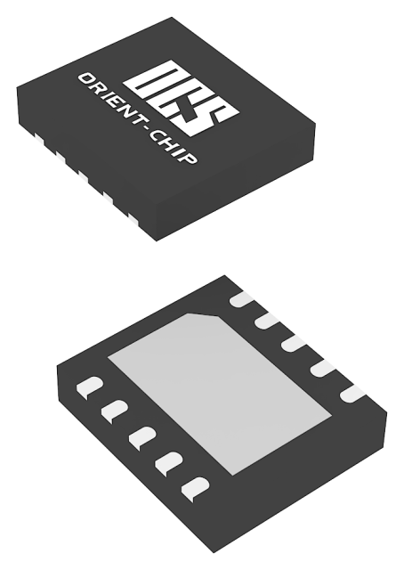
- PackageTDFN3030-10L
- Operating Temperature-40℃~105℃
- Sensorless control√
-
Overview
-
Features
-
Specifications
-
Package & Ordering
-
Apply
overview
The OCH2360 provides all the circuitry for sensor-less speed control of three-phase brushless DC motor. The Sine-wave Driver method will be better sound quality. The controller functions include start-up circuit, back-EMF commutation control, Pulse Width Modulation (PWM) speed control, lock protection, and thermal shutdown circuit. The OCH2360 is suitable for both game machine and CPU cooler that need silent drivers. It is available in TDFN3030-10L package.
Applications
NB、AR、VR、AIOWireless ChargerBLDC Motor
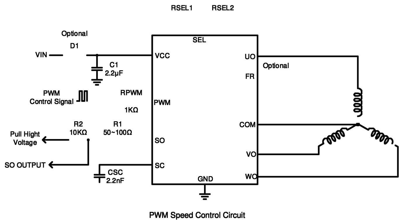
Typical Application Circuit
features
-
 PWM Sine-Wave Driver
-
175°/150°sinusoidal drive for low audible noise
-
Three-Phase Sensor-Less Drive
-
Adjustable Forced Commutation Frequency (For Start-up)
-
Built-In External PWM Speed Control
-
Built-In Quick Start Function
-
FG、1/2FG Or 1/3FG Signal Output
-
Power Saving Function
-
Built-In Lock Protection and Auto Restart Function
-
Built-in Thermal Protection Circuit
-
TDFN3030-10L package
-
Lead Free and Green Device Available (RoHS Compliant)
Specifications
Type
Parameter
Type
Parameter
-
Motor type1.8V~6V
-
Peak current1.3A
-
Fan Safety Rated Current5V-700mA
-
PackageTDFN3030-10L
-
Operating Temperature-40℃~105℃
-
Sensorless control√
-
FR Function√
-
PWM/VSP Speed ControlPWM
-
Lock Auto-Restart√
-
FG RDFG 1/2FG 1/3FG
-
windowing control√
Package & Ordering
Ordering Information
| Part Number | Package Type | Packing Quantity | Temperature | Eco Plan | Lead |
|---|---|---|---|---|---|
| OCH2360VAD | TDFN3030-10L | 3000pcs/Reel | -40 ~ +105°C | ROHS | Cu |
Package & Pin Definition

| Pin Name | Pin Number | Pin Function |
|---|---|---|
| VO | 1 | Driver Output Pin. Output signal for driving motor phase V |
| WO | 2 | Driver Output Pin. Output signal for driving motor phase W |
| VCC | 3 | Supply Voltage Input Pin. |
| FR | 4 | Motor Spin Direction Control Pin. Fixed High Level Input (FR=VCC): U→V→W; Fixed Low Level Input (FR=GND): U→W→V |
| SC | 5 | Start-up Commutation Time Setting. Connect a capacitor to GND to set start-up commutation time |
| PWM | 6 | PWM Signal Input Pin. Input PWM signal to control rotation speed |
| SO | 7 | Rotation Speed Output or Rotation Detection Output. This is an open-drain output |
| SEL | 8 | Mode Setting. Use a voltage divider from VCC to set SEL pin voltage for setting |
| COM | 9 | Motor Neutral Point Input Pin |
| UO | 10 | Driver Output Pin. Output signal for driving motor phase U |
| GND | Exposed Pad | Ground Pin |

