


OCH1919
3-Axis Electronic Compass
- VDD1.65~1.95V
- IDD(AVG)0.6uA@powerdown
- GAUSS(MIN)-49Gauss
- GAUSS(MAX)49Gauss
- PackageWLCSP4
- Operating Temp.-30℃~85℃
-
Overview
-
Features
-
Specifications
-
Package & Ordering
-
Apply
overview
OCH1919 is 3-axis electronic compass IC with high sensitive Hall sensor technology. Small package of OCH1919 incorporates magnetic sensors for detecting terrestrial magnetism in the X-axis, Y-axis, and Z-axis, a sensor driving circuit, signal amplifier chain, and an arithmetic circuit for processing the signal from each sensor. Self-test function is also incorporated. From its compact foot print and thin package feature, it is suitable for map heading up purpose in Smart phone to realize pedestrian navigation function.
Applications
Smart phoneSmart WatchPad Consumer Application
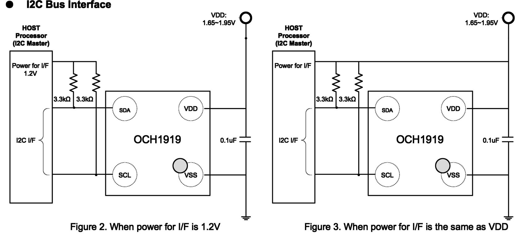
Typical Application Circuit
features
-
 3-axis magnetometer device suitable for compass application
-
Built-in A to D Converter for magnetometer data out
-
16-bit data out for each 3-axis magnetic component; Sensitivity: 0.15 µT/LSB (typ.)
-
Serial interface: I3C bus interface; Compliant with MIPI I3C v1.0 specification
-
Operation mode: Power-down, Single measurement, Continuous measurement and Self-test
-
DRDY function for measurement data ready
-
Magnetic sensor overflow monitor function
-
Built-in oscillator for internal clock source
-
Power on Reset circuit
-
Self-test function with internal magnetic source
-
Built-in magnetic sensitivity adjustment circuit
-
8 FIFO data buffer
-
Operating temperatures: -40˚C to +85˚C
-
Operating supply voltage: +1.65V to +1.95V
-
Current consumption: Power-down: 0.56 µA (typ.); Measurement: Average current consumption at 100 Hz repetition rate: 1.3 mA (typ.)
-
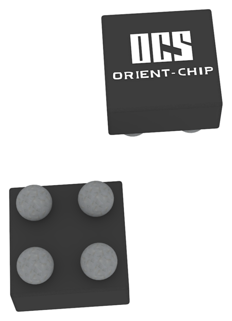
Package: 4PIN WL-CSP:0.74mm*0.74mm*0.55mm
Specifications
Type
Parameter
Type
Parameter
-
VDD1.65~1.95V
-
IDD(AVG)0.6uA@powerdown
-
GAUSS(MIN)-49Gauss
-
GAUSS(MAX)49Gauss
-
PackageWLCSP4
-
Operating Temp.-30℃~85℃
-
AEC-Q100NO
Package & Ordering
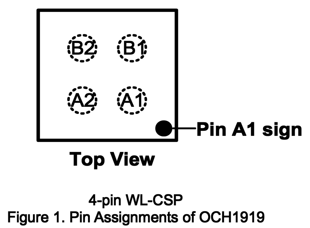
Package & Pin Definition
| Pin Name | Pin No. | I/O | Pin Function |
|---|---|---|---|
| VSS | A1 | - | Ground pin. |
| SCL | A2 | I | Control clock input pin. |
| VDD | B1 | - | Positive power supply pin. |
| SDA | B2 | I/O | Control data input/output pin. Input: Schmitt trigger, Output: Open-Drain and Push-Pull. |


